2023: Renovation of circuits
The 2 trips I made with the boat and the various problems I encountered prompted me to include repairs to the fuel, water and electricity networks right from the start of the project.
Indeed, the breakdowns followed one another:
- diesel: following the last major breakdown and given the complexity of the circuit with 2 tanks, I preferred to simplify it as much as possible to make it easier to read the circuit and therefore to face any problems
- water: the hot water circuit suddenly leaked in Denmark, forcing me to turn off the hot water. The pipes were old, still covered with cottony insulation
- electricity: this was the boat's big black spot: a single minor breakdown with the alternator, which the engine oil eventually rendered inoperative. But faced with what was certainly the original installation, embellished with the additions of each of the owners, the circuit was becoming dangerous: some of the switches had been short-circuited, giving a false impression of safety by keeping live parts that you think are insulated.
Fuel circuit
This system, which initially consisted of 2 tanks (each with around 250 litres), multiple filters and valves, seemed too complicated to me and, above all, oversized for sailing. So I decided to keep one single tank for diesel, the one on the starboard side of the boat because it's on the diesel injection side. The other tank is better placed to supply the water system (water heater, galley, bathroom).
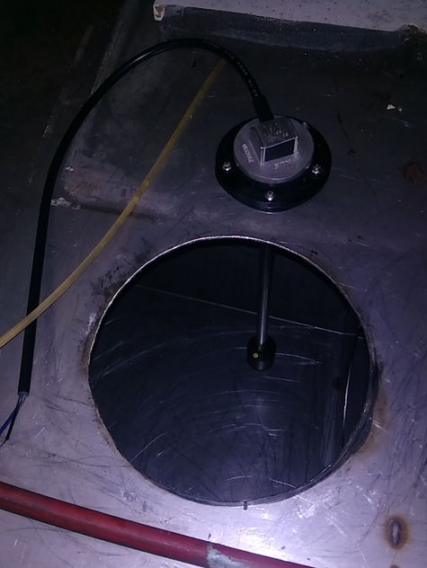
This stainless steel tank was neither fitted with inspection hatches nor a level sensor. Not very practical for cleaning it or finding out how much was left in it! Equipped with internal reinforcements to prevent the liquid from shifting around too much, the tank is divided into 3 zones. I fitted 2 inspections hatches in each ends of the tank, suitable for diesel fuel, as well as a level sensor (combined with a "FUEL" gauge on the dashboard).
After several attempts, and the specific hole saw wearing out quickly, the tried and tested cutting technique was to cut a smaller hole with a commercial metal hole saw, then enlarge the hole with a grinder (radially up to the line, then tangentially to the line to remove the flakes formed).
Fearing sparks in the tank and the risk of explosion, I connected the hoover to the tank's ventilation nozzle to remove as much diesel vapour as possible. But it seems that this fuel is sufficiently safe (flash point at 55°C, so diesel below this temperature doesn't produce flammable vapours, unlike petrol for which the flash point is -40°C), and even without the hoover I didn't have any problems, despite being really apprehensive at first.

I then moved on to the pure pleasure part (I'm sure you'll envy me ;-) ):
- sucking up the diesel residue with a manual oil drain pump
- sucking up and scraping off the remains of bacteria, forming a sort of viscous placenta
- cleaning with an industrial degreaser (Cetexalt VG) that disperses hydrocarbons. After 2 cleanings, I was able to rinse with water, which was also vacuumed to leave the tank dry
All of which involved various and sundry contortions, making me feel both too big (to bend easily) and too small (to reach the bottom)!

Latest modifications to this circuit:
- installation of a CAV type pre-filter with decanter at the tank outlet (to separate the water still present in the diesel)
- installation of a finer filter (6 microns) after the injection pump (the diesel heater is also fed from this 2nd filter)
- and above all, changing the hoses and tightening the clamps (editor's note: the subject of the last breakdown ;-) )
The challenge here was to find the filtration information (most manufacturers don't mention this information on their technical sheets/product) and the compatibility with the filter supports I already had and wanted to keep because they suited the engine.
Water circuit
As mentioned, this circuit was old and a leak in the hot water circuit convinced me that a complete replacement was necessary.
The initial water circuit consisted of 3 tanks in the saloon: 2 flexible tanks under each of the benches + 1 rigid tank under the floor. A 'piano' of valves was used to manage these tanks, but some valves were blocked or broken.
As mentioned above, I removed these multiple tanks to use just one, the port tank previously dedicated to diesel.

An inspection hatch was already present in the centre of the tank. I added 2 at each ends of the tank for better access.
Here too I emptied and cleaned the tank, which is made of steel on this side. It will certainly need changing at some point. I'm thinking of doing it when I change the engine, because extracting the tank is complicated otherwise.
The pump was located under the fridge, not very accessible. I preferred to install a CP plate in the engine area, taking advantage of the relocation of the batteries in the trunk under the chart table. This allows me to group the pump, expansion tank and water heater in the same area.

Electrical circuits
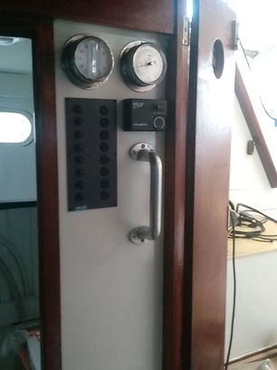
As indicated at the top of the page, this circuit was a mixture of the original installation and successive additions, certainly over the course of different owners (see photo below). Faced with some short-circuited switches, and rather than spending days identifying the circuits, I preferred to remove everything and start again from a sound base.
As soon as the renovation began, I called on Seatronic to design the circuit and provide me with electrical plans, as I wanted to carry out the installation myself. Armed with patience, I got the final plans after just over a year of exchanges and successive versions. What's special about this circuit is that there are 2 electrical panels: one in the cockpit for everything to do with navigation (lights, autopilot, electronics, windlass, foghorn, etc.), and another in the companionway for everything to do with life on board (pumps, fridge, hi-fi, lighting, water heater, etc.).
I also replaced some equipment that wasn't suited to my use (rotating porthole, which interfered with the course compass, outdated electronics replaced by Raymarine components that I prefer, replacement of various gauges with new components, etc.).

The installation is now easy to read, as it has plans and has been designed as a lot, tidier and, above all, up-to-date.

Putting the cables in place wasn't easy, as I was new to this activity. After a few tries, I found it easier to push the cables into the sheaths (2-3 depending on the sheath) by making them hang down, then to put the cabled sheaths in place and run them from the distribution points to the switchboards.
I pulled and connected the large connections first (shore power, batteries, alternator, windlass, switchboards) using straight or angled lugs crimped with HX-50B pliers.
Then I made the distribution downstream of the switchboards. There were very few crimps here, as the cables were often connected directly to the rail-mounted switchboard terminals.
It was only at the end that I switched on the power and was able to test my work: 2 bad contacts on 2 lamps due to badly crimped lugs that I replaced with quick connectors. Everything else worked on the first try, to my great satisfaction!


